Contents
What are Construction Documents?
Construction documents may not seem like the most glamorous part of architectural design. All the ‘fun’ stuff - the model making, sketching, conceptual conversations and wild iterations - happens earlier in schematic design. Even the term ‘construction documents’ sounds boring.
But, construction documents (CDs) are an important part of the architectural process, and provide their own unique opportunities for the designer. Construction documents are directions from the Architect to the Contractor. These documents describe precisely how the Contractor will make the Architect’s design become a built object - through drawings and specifications.
What is Construction Documentation?
Here, all the details come together, and construction documents serve two basic purposes: to obtain a building permit, and to get the design built. These may be delivered in two types of construction documents - a permit set and a construction set.
While both construction document sets need to be very detailed, it is common practice for the permit set to be delivered prior to the construction set. In so doing, any issues that arise during permitting can be addressed and corrected in the construction set. In order for a completed building to receive its final certificate of occupancy from the local authority having jurisdiction, the building must closely match the construction documents submitted in the permit set.
What is the Purpose of Construction Documents?
The purpose of construction documents is to get the design built. These are contract binding documents which describe precisely how the design shall be built: methods, materials, building systems, components. The construction documents describe precisely, in both large and small scales, every facet of the building design. Good construction documents provide the Contractor the most comprehensive understanding of the Architect’s intent.
What is Included in Construction Documents?
There are two things included in Construction Documents: Drawings and Specifications. All Construction Documents follow this standard, which helps the reader to know where to look among the hundreds of pages of architectural drawings and specifications. Each affiliated building practice provides both types of construction documents: Architecture, Structural, Mechanical, Electrical, Plumbing, Landscape Architecture, and Civil.
Construction Drawing typically include:
- General Sheets: These are the beginning of the construction documents set. The general drawings include the cover page, building and zoning code analysis, life safety plans, and accessibility and sustainability standards if required.
- Civil Engineering Sheets: These drawings include the Civil Engineer’s notes, the grading and utilities plans, and other details.
- Landscape Architecture Sheets: These drawings are submitted by the licensed Landscape Architect. The landscape architecture drawings include plans, sections, and details, in order to effectively communicate to the Contractor and Subcontractors how to construct the various landscape elements. There is usually coordination required between the Civil Engineer and Landscape Architect.
- Structural Sheets: The licensed Structural Engineer’s drawings provide structural plans, calculations, and details - from an entire level’s beam system, to the detailed connection between structural elements. Detailed drawings and calculations for each type of structural system in the project are required.
- Architectural Sheets: The architectural drawings graphically communicate (in plan, section, elevation, and details) the architectural components of the building design. Architects are most familiar with these drawing types, but there are similarities in drawing types among all disciplines.
- Plumbing Sheets: The plumbing drawings will show the locations and sizes of all inbound and outbound water supply. A plan for each level shows every pipe, faucet, and drain. Diagrams, details, and schedules also communicate how these components work together to provide a functional plumbing system in a building.
- Mechanical Sheets: The mechanical engineer’s drawings will show the locations and sizes of all mechanical equipment in an architectural design. This includes the size and layout of all exposed or concealed ductwork, as well as the location of each vent, heating unit, cooling unit, and thermostat.
- Electrical Sheets: These drawings will show the locations of all power outlets, sources, light fixtures, and switches. As we see growing trends towards energy efficiency after occupancy in buildings, the electrical drawings may also account for energy and sustainability compliance. Typically, lighting plans and power & voltage plans are provided for each level of the building, as well as a sheet devoted to power calculations.
The Construction Drawing set is regularly hundreds of pages long, at standard architectural sheet sizes. Required sheet sizes vary by jurisdiction, but are typically one of these standard sheet sizes:
- ARCH A - 9 x 12 inches
- ARCH B - 12 x 18 inches
- ARCH C - 18 x 24 inches
- ARCH D - 24 x 36 inches
- ARCH E - 36 x 48 inches
Schedules are an important component of construction documents . The most common schedules to appear in construction documents are the door, hardware, window, and equipment schedules. The United States National CAD Standard contains standard formats for schedules in construction drawings and specifications. The schedule helps the Contractor to understand the location of every building component in the architectural design.
Both the drawings and specifications follow standard orders, respectively (the standard for drawing orders and types are covered later in this essay). MasterFormat is a specification standard from the Construction Specifications Institute. This is a common method of specification in construction documents . MasterFormat regularly updates their specification information and templates to allow all designers and engineers to produce building specifications which are safe, sustainable, and long-lasting.
The specifications accompany the construction drawings when submitted for permitting and for construction. Like the construction drawing set, there is a standard for organization in specifications so that all project team members can easily find what they are looking for. Each design team and consultant is responsible for providing specifications to accompany their drawing sets.
Specifications are divided into Divisions, beginning with the contract language for the entire Project team, then the architectural and structural specifications, with consultant specifications at the end.
Entire Project Team:
- Division 00 - Procurement and Contracting Requirements
- Division 01 - General Requirements
Structural (and Architectural)
- Division 02 - Existing Conditions
- Division 03 - Concrete
- Division 04 - Masonry
- Division 05 - Metals
- Division 06 - Wood, Plastics, Composites
Architectural (and Interiors)
- Division 07 - Thermal and Moisture Protection
- Division 08 - Openings
- Division 09 - Finishes
- Division 10 - Specialties
- Division 11 - Equipment
- Division 12 - Furnishings
- Division 13 - Special Construction
- Division 14 - Conveying Equipment
MEP (Mechanical, Electrical, Plumbing)
- Division 21 - Fire Suppression
- Division 22 - Plumbing
- Division 23 - Heating, Ventilating, and Air Conditioning (HVAC)
- Division 25 - Integrated Automation
- Division 26 - Electrical
- Division 27 - Communications
- Division 28 - Electronic Safety and Security
Landscape and Civil
- Division 31 - Earthwork
- Division 32 - Exterior Improvements
- Division 33 - Utilities
The relationship between specifications and drawings is important in the Construction Document set. There should be close coordination of information between both, to provide the most synchronized description of all the elements of a building, with as little conflicting information as possible. Coordination of the specifications and drawings allows for accurate bids, and in turn affords a more seamless construction process.
What Order Do Construction Drawings Go In?
Construction document drawings follow a standard order. Typically, construction drawings follow the United States National CAD Standard. In this standard, the lower right hand corner of each drawing sheet contains a series of letters and numbers (the sheet number). The sheet number lets the reader know where they are in the drawing set, and allows the reader to know where to look in the drawing set for specific information.
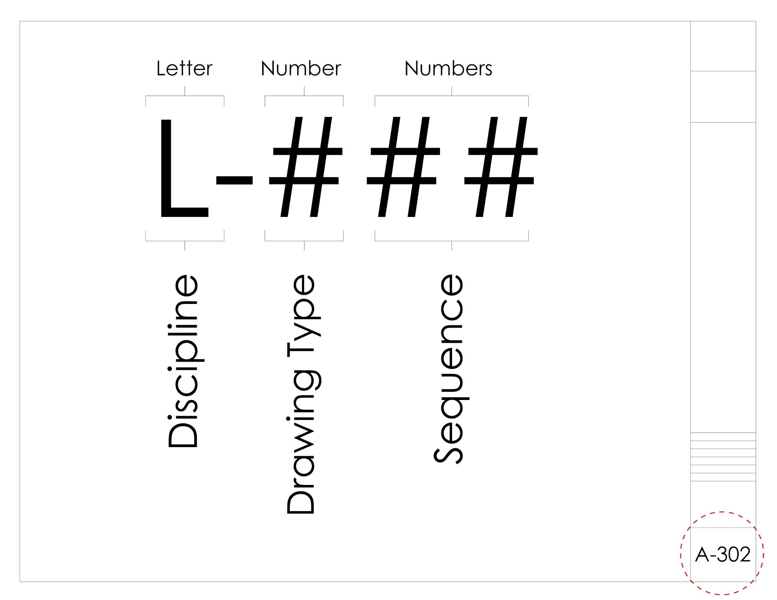
The first part of the sheet number is a letter which lets us know the discipline for the drawing. These disciplines are arranged in the same order (United States National CAD Standard), for consistency in construction documents. This helps all stakeholders: designers, engineers, contractors, the permitting office, and owners.
- G - General: Sheet list, symbols, summary, life safety and code analysis.
- C - Civil
- L - Landscape
- S - Structural
- A - Architectural
- F - Fire Protection
- P - Plumbing
- M - Mechanical
- E - Electrical
- T - Telecommunications
There are other disciplines which can be included, such as H - Hazardous Materials; B - Geotechnical; I - Interiors; W - Distributed Energy; O - Operations; Z - Contractor/Shop Drawings.
The second component of the sheet number is a number, which lets us know the type of drawing. This organizes the discipline’s drawings into a consistent, standard sequence of drawing types.
- 0 - General (legends, symbols, general notes)
- 1 - Plans
- 2 - Elevations
- 3 - Sections
- 4 - Large Scale Drawings: plans, elevations, sections
- 5 - Details
- 6 - Schedules and Diagrams
- 9 - 3D Drawings (isometric, perspective, renderings)
7 and 8 are reserved for user defined drawing types.
The last two numbers represent the sequence in the sheet type for each discipline from 01 to 99. These numbers may have gaps to allow additions in future drawing set deliverables.
How to Read Construction Plans?
Each building practice will issue construction plans in the drawings: Landscape Architecture, Civil Engineering, MEP (Mechanical, Electrical, Plumbing Engineering), Structural Engineering, and Architecture. While the information contained in each of these plan drawing sets is different, the basis of these drawings is the plan.
There are a few key elements in construction plans: Dimensions, Scales, and Annotations.
Accurate dimensions are critical to representation of the project in all architectural drawings, starting with the plan. Accurate dimensions help avoid discrepancies and conflicts between different drawings and disciplines. Firms will regularly adopt a standard method of dimensioning, for consistency among all drawing types. These standards may include:
- Consistent dimensioning from a fixed reference point, such as centerline or exterior/interior finish.
- Hierarchy of dimensioning, only dimensioning important information in the drawing.
- Not repeating dimensions of the same element across multiple drawings.
- Horizontal dimensioning in plan drawings, and vertical dimensioning in section and elevation drawings.
- Double and triple checking dimensioning before submitting construction documents.
Choosing an appropriate drawing scale for the information being presented is important. Overall site plans may be presented at a scale of 1”=40’-0”. Floor plan drawings may be presented at a typical scale of 1/16”=1’-0”, or 1/8"=1’-0” for smaller buildings. Construction details, which show a lot of information in one drawing, may be presented at a scale of 1-1/2"=1’-0” or even larger. Line weight appropriate to the scale of the drawing should always be considered, as it will change across drawing scales.
Annotations appear in almost every drawing in the construction document drawing set, and are used to convey concise information about the materials or components of the building system presented. These short descriptions are elaborated in the specifications, which provide a more comprehensive explanation of the materials, components, and building systems, as well as the installation and execution procedures for each.
Who's Involved in Construction Documents?
The entire project team is included in construction documents: the Owner, the Contractor, the Architect, the Civil Engineer, the Landscape Architect, the Structural Engineer, the Mechanical, Electric and Plumbing Engineer (usually the same company consults for these three - MEP).
Additionally, a project team may hire other consultants for Acoustics, Building Envelope, Fire Suppression and Fire Alarms, Geotechnical, and ADA.
Construction Documents Checklist
- Review unresolved issues from previous design phases
- Review and update schedules of completion dates with project team and Owner
- Identify all construction documents necessary for project and due dates
- Check with jurisdictional regulatory agencies for compliance and review
- Coordinate all work from project team, including consultants
- Develop and disseminate formats for title blocks, sheets, specifications, schedules
- Review and check for code compliance in project design
- Determine final delivery system method
- Verify Owner’s acceptance of all design and consultant elements and cost estimates
- Review and verify potential bidders with Owner
- Print a scaled draft of all construction documents for review prior to delivery
- Licensed Architect and Engineer’s Seals stamped on documents
- Submit construction documents for delivery
Examples of Construction Documents
Examples of Domestic Building Design Documentation
Jill Sorson Kurtz - Archinect - Examples of Construction Documents
John Anthony Drafting and Design - Examples of Construction Documents
Tesla Outsourcing Construction Documentation Examples
William Webb Architect - Examples of Construction Documents
Additional Resources:
AIA / NCARB Emerging Professional’s Companion: Construction Documents
Construction Specifications Institute
Lynda.com - Construction Documents
United States National CAD Standard
Get started with Monograph today to improve your firm's performance and project management.